Mono 3d template usage
It used the 2d feature to extract the 3d position of the object.
(reference https://docs.pickit3d.com/en/latest/examples/build-a-showcase-demo-with-a-m-camera-and-suction-cup.html)
Use Case
TODO: Upload Benz Battery project video after done.
Requirement
TODO: Abstract Benz Battery project Requirements after done.
Mounting instructions
TODO: Abstract Benz Battery project instructions after done.
Setting up the picking pipeline
Calibrate the camera
Nest step is the Hand-Eye Calibration. This process must use the DA Calibration nodes. It generates the relative positions between the robot flange and the camera. This relation is used to transform the object pick points into robot coordinates. Details can be found in .. _my-reference-label: TODO: Add DA Calibration reference rst.
Define the feature and train the object
After Hand-Eye Calibration, head to mono-3d and follow the instructions to define features and train/set an object model.
Teach the picking pose
- Teach picking pose process is made to find the relative positions between the robot flange and the object. Once this relation is generated, the relative position between tool and object will remain the same while picking.
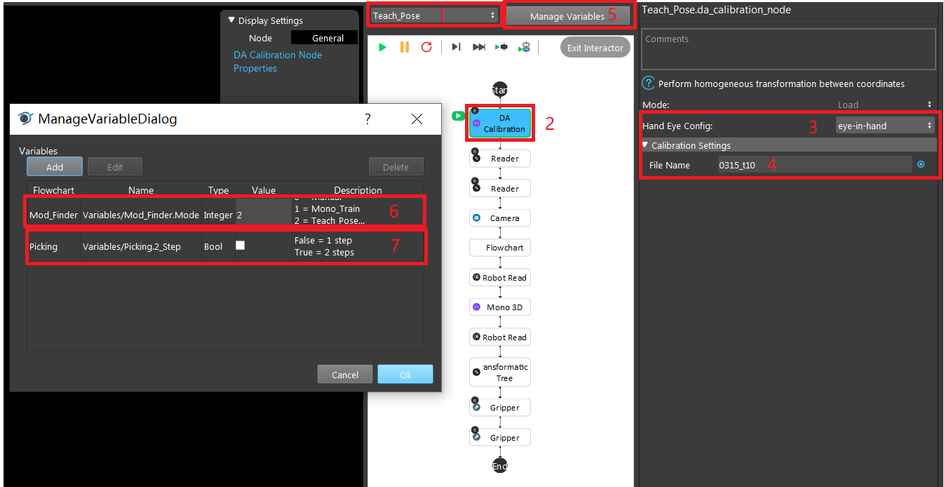
Head to the Teach_Pose flowchart and click DA Calibration node. On the configuration window, select Hand Eye Config setting to be eye-in-hand, and enter the DA calibration output file name.
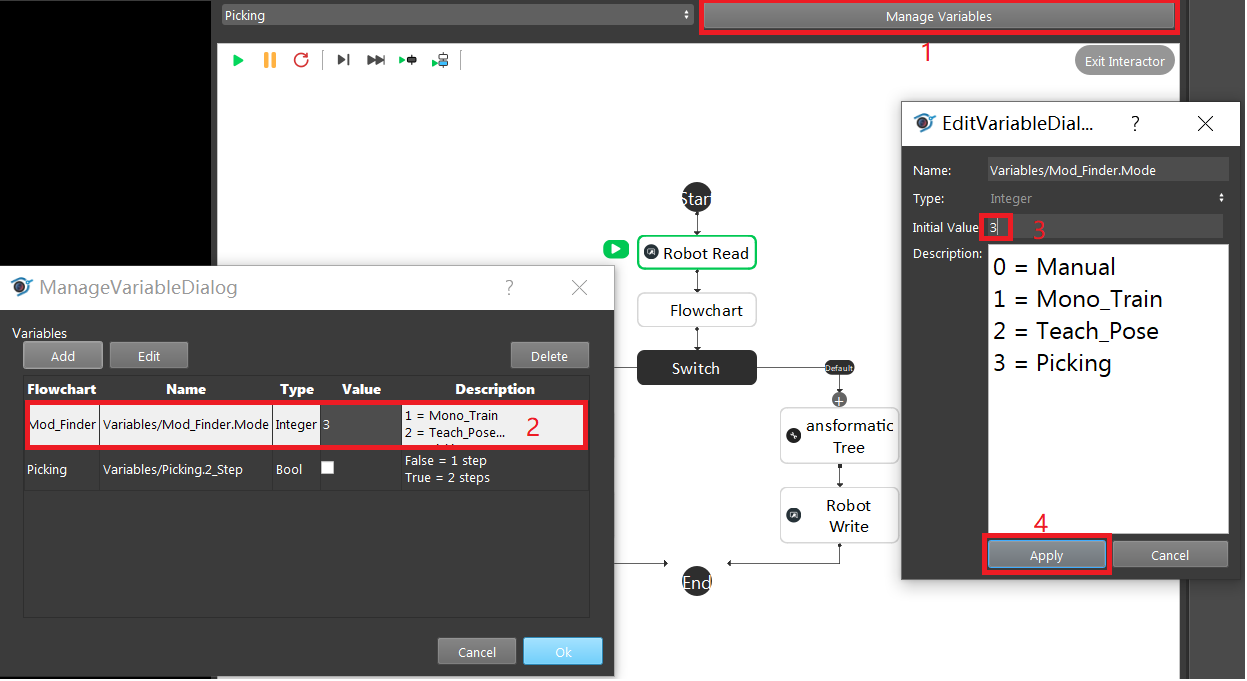
Click Manage Variables button and set Mode to 2, and 2_Step to False by unchecking the value box.
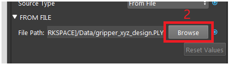
Click on the first reader node and load browse the gripper mesh file. Then click on the second reader node and load the object mesh file.
Hint
If there’s no gripper and object mesh file matching the real ones, load any mesh file.
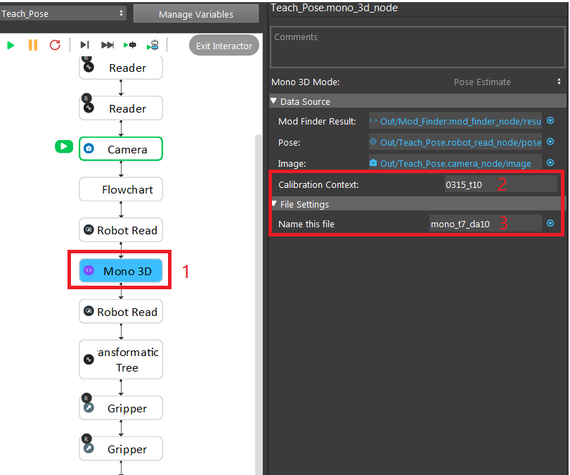
Click on the Mono 3D node pose estimate mode, set the calibration Context and mono training file name just like what was defined in Detection flowchart.
Use Next Step to run the flowchart step by step, first Robot Read node require the robot to send the detection pose which is the pose where the camera captures. The second Robot Read node require the robot to send the picking pose of how gripper should pick the object.
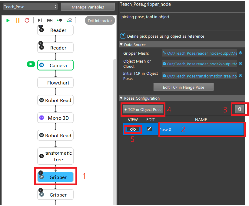
After running the first Gripper node, click on it, and click on the existing pose, click the trash icon button to remove previously saved poses. Then click ** + TCP in Object Pose**, and click the View button to see preview of relative position between tool and object.
Note
Ignore the second gripper. It is used for 2 step picking.
Execute the picking
Click Manage Variables button and set Mode to 3, and 2_Step to False by unchecking the value box.
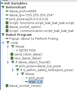
Get Robot picking script ready and run the Picking flowchart. UR Picking Experiment Script example below:
Flowchart Summary
Manual
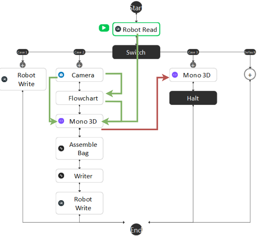
The data flow for this flowchart is basically gathering the camera captured image, mod finder result, and robot pose into Mono 3D Accumulate mode and use Mono 3D final mode to generate a training file.
Mono Train
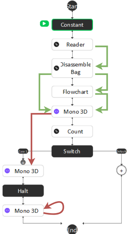
The data flow for this flowchart is similar to Manual. Instead of acquiring image from camera and pose from robot read, it gets data from assembled bag, plus mod finder result into Mono 3D Accumulate mode and use Mono 3D final mode to generate a training file. If Mono 3D Set feature mode is used, none of the data will be needed.
Mod Finder
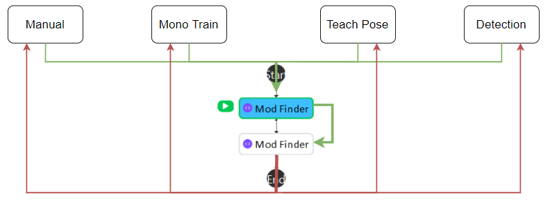
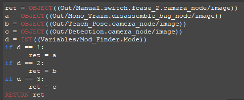
The image input for Mod Finder nodes comes from different flowchart depending on the value of Variable.Mode. Then Second Mod Finder node uses first one as it’s reference fixture which anchors the geo features. Then the output goes back to different flowcharts.
Teach Pose
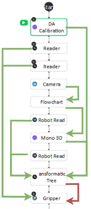
Firstly, DA Calibration node will load the relative position between camera and flange. Secondly, Camera node will provide image for Mod Finder flowchart which will generate geo features in camera 2D location for Mono 3D pose estimate mode. First Robot Read node will read the robot pose for detection pose, second Robot Read node will read the robot pose for picking pose, and both will be passed to Transformation Tree* node. **Mono 3D pose estimate mode will generate the object in camera 3D location for Transformation Tree node. Afterwards, Transformation Tree node will calculate the Flange in object relative position and pass it to Gripper node. Since Gripper node is added to recipe, the saved pose will be loaded through Load Recipe node in Detection flowchart.
Detection
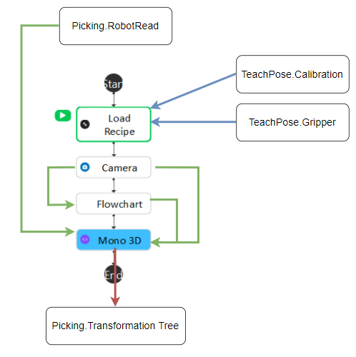
The Load Recipe node will load Calibration and Gripper node output from Teach Pose flowchart. Then Mono 3D will gather detection pose, image, and mod finder result to generate the actual object in camera location.
Picking
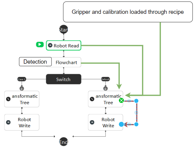
The Robot Read node will receive the detection pose and pass it to Transformation Tree node. Mono 3D node in Detection flowchart will provide object in camera 3D location for Transformation Tree node. The Gripper and DA Calibration node will be loaded through Load Recipe node and provide camera in tool and tool in object location. Finally Transformation Tree node will generate the tool in base and guide robot to pick the object.
Cautions
2 Step Picking
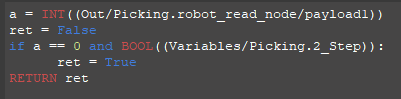
This document is only for 1 step picking. Two step picking is only for high accuracy requirement which the first step is to move camera to a better detection position. In the switch node of Picking flowchart, case_1 is to generate the better detection pose, and payload from robot will be needed to switch first and second step. The 2 Step Picking will be enabled by changing the Variable.Mode to True.
The Mod Finder nodes input image is decided by the Variable.Mode.
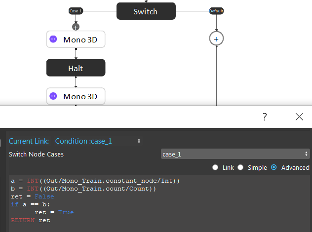
The Switch node in Mono Train flowchart will be evaluated to True if the Count node in front of it is equals the number of bags set in Constant node.
The Manual flowchart will be using the same robot script as Manual Calibrations. The switch node will check the received command from Robot Read node.